并联四足机器人位置控制
参考学习资源
【【教程】成本1K!从0教你DIY无刷四足机器人~灯哥无刷四足一代实验版开源啦!!!】 https://www.bilibili.com/video/BV1kV411i76z/?share_source=copy_web&vd_source=4eaa4760820b4cda603e510d556578ac
【灯哥0基础DIY四足机器人指南(8)–用Matlab画出摆线步态曲线】 https://www.bilibili.com/video/BV1KQ4y1K7aV/?share_source=copy_web&vd_source=4eaa4760820b4cda603e510d556578ac
四足机器人并联腿足端轨迹matlab仿真-CSDN https://blog.csdn.net/qq_36942736/article/details/106580465?fromshare=blogdetail&sharetype=blogdetail&sharerId=106580465&sharerefer=PC&sharesource=qq_52769953&sharefrom=from_link
华北舵狗王带你一起做四足机器人2(Moco-8四足机器人控制算法简介) - 华北舵狗王的文章 - 知乎
https://zhuanlan.zhihu.com/p/69869440
【灯哥0基础DIY四足机器人指南(9)–手把手教你写出小跑步态程序】 https://www.bilibili.com/video/BV1YD4y1D7k6/?share_source=copy_web&vd_source=4eaa4760820b4cda603e510d556578ac
[灯哥开源—四足机器人]程序算法讲解与STM32移植——PA_TROT和PA_WALK讲解和trot步态,walk步态,步态规划-CSDN https://blog.csdn.net/weixin_41659552/article/details/113738017?fromshare=blogdetail&sharetype=blogdetail&sharerId=113738017&sharerefer=PC&sharesource=qq_52769953&sharefrom=from_link
【干货|开源MIT Min cheetah机械狗设计(五)】|机械狗步态规划(重点) - 陈不陈的文章 - 知乎
https://zhuanlan.zhihu.com/p/639128926
【四足机器人项目实战】|四足机器人步态规划与相位控制实现 - RoboticsTechLab的文章 - CSDN
https://download.csdn.net/blog/column/11523325/122047921
MIT Cheetah 完整开源代码与论文简介 - 廖洽源的文章 - 知乎
https://zhuanlan.zhihu.com/p/79391139?utm_psn=1874912895365672960
四足机器人优化方法初探:快速移植MIT Cheetha MPC控制代码 - 华北舵狗王的文章 - 知乎 https://zhuanlan.zhihu.com/p/450008168?utm_psn=1874923719606009856
看论文:
yxy, 张国腾
VMC论文阅读笔记_摆动相位轨迹_公式和代码 - lcccccc的文章 - 知乎
https://zhuanlan.zhihu.com/p/687733214
webots四足机器人建模教程:
【实例 手把手搭建Webots四足机器人(机器狗)】 https://www.bilibili.com/video/BV1u44y1f7oU/?share_source=copy_web&vd_source=4eaa4760820b4cda603e510d556578ac
Webots& 四足模型搭建&简单的测试程序Demo - lcccccc的文章 - 知乎
https://zhuanlan.zhihu.com/p/686867275
摆线足端轨迹和运动学逆解
关于摆动腿足端的轨迹,有以下期望:
1)在足端刚开始离地和将要触地时,希望足端的速度很小,并且在xy平面没有滑动趋势。
2)足端在轨迹的中段时运动迅速。
3)足端轨迹足够平滑,不存在波动。
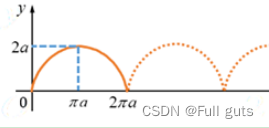
常用的足端估计有多项式曲线,分段直线和摆线。其中多项式曲线可以画出光滑且复杂的轨迹,但其中各个参数的计算比较复杂。分段直线轨迹虽然设计比较简单,但是轨迹不够光顺平滑。摆线轨迹虽然不能灵活的修改轨迹的形状,但是表达式简单且参数具有明显的几何意义,比较容易推导。
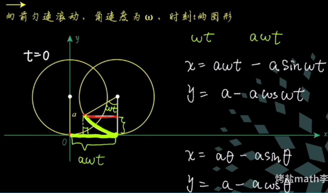
摆线(Cycloid),又称旋轮线、圆滚线,在数学中,摆线被定义为,一个圆沿一条直线运动时,圆边界上一定点所形成的轨迹。对于四足机器人,让四条腿以一定的相位差跑出这条曲线,四足机器人就有了前进的能力。
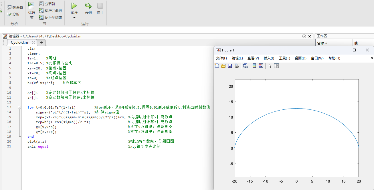
用Matlab画出摆线步态曲线
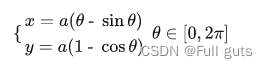
摆线方程
原始方程
推导
对原始方程处理
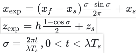
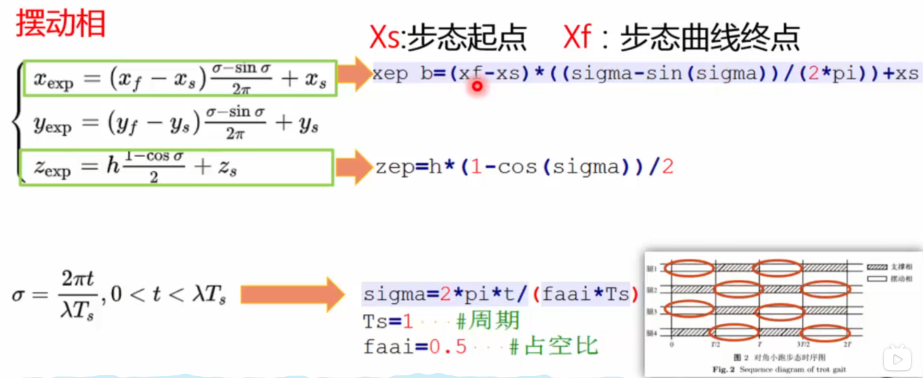
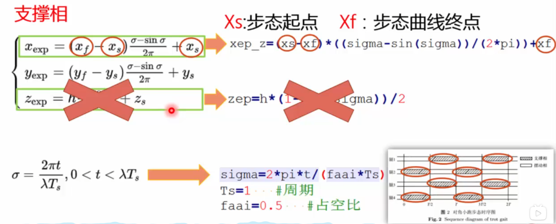
Xs:水平方向足端当前起点位置 Xf:水平方向足端期望落足点位置 (xf-xs)/2pi=a
Zs:竖直方向足端当前起点位置 Zf:水平方向足端期望落足点位置
Ts:步态周期,λ:支撑相占空比, h:摆线高度 h=2a=(xf-xs)/pi
t:离散时刻点,每个点对应摆线轨迹上的一个坐标
θ=2pi*(t/λTs)
1
2
3
4
5
6
7
8
9
10
11
12
13
14
15
16
17
18
19
20
21
| clc;
clear;
Ts=1;
fai=0.5;
xs=-20;
xf=20;
zs=0;
h=30;
x=[];
z=[];
for t=0:0.01:Ts*(1-fai)
sigma=2*pi*t/((1-fai)*Ts);
xep=(xf-xs)*((sigma-sin(sigma))/(2*pi))+xs;
zep=h*(1-cos(sigma))/2+zs;
x=[x,xep];
z=[z,zep];
end
plot(x,z)
axis equal
|
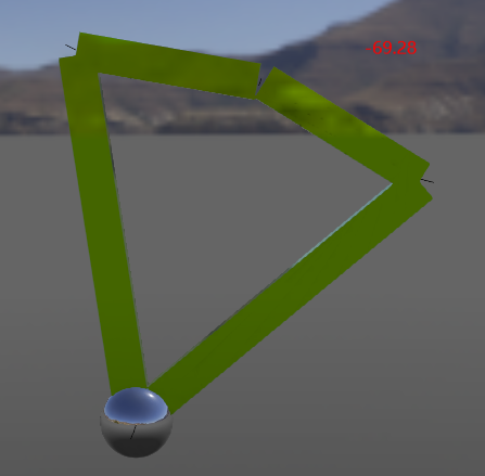
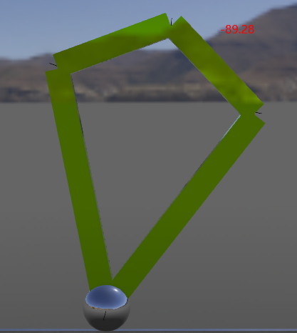
在Webots实现单条腿按摆线足端轨迹运动,占空比取0.5:
1
2
3
4
5
6
7
8
9
10
11
12
13
14
15
16
17
18
19
20
21
22
23
24
25
26
27
28
|
void trot()
{
if (t < T_s * fai)
{
sigma = 2 * pi * t / (fai * T_s);
zep = h * (1 - cos(sigma)) / 2;
xep_b = (xf - xs) * ((sigma - sin(sigma)) / (2 * pi)) + xs;
xep_z = (xs - xf) * ((sigma - sin(sigma)) / (2 * pi)) + xf;
x_1 = xep_z;
y_1 =0+height;
}
else if ((t > T_s * fai) && (t <= T_s))
{
sigma = 2 * pi * (t-fai*T_s) / (fai * T_s);
zep = h * (1 - cos(sigma)) / 2;
xep_b = (xf - xs) * ((sigma - sin(sigma)) / (2 * pi)) + xs;
xep_z = (xs - xf) * ((sigma - sin(sigma)) / (2 * pi)) + xf;
x_1 = xep_b;
y_1 = zep+height;
}
}
|
不同height的作用效果如下,可见height就是关节的离地高度,height的绝度值越大,关节离地越远
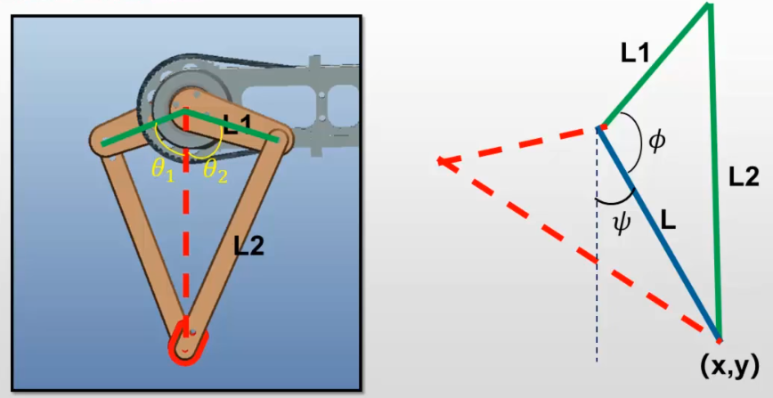
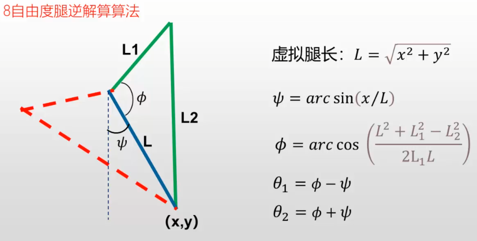
运动学逆解
通过足端轨迹生成足端的x,y坐标,然后运动学逆解得到两个关节电机对应旋转的角度即可控制足端实现预定轨迹。
1
2
3
4
5
6
7
8
9
10
|
void nijie()
{
l = sqrt(x_1 * x_1 + y_1 * y_1);
psi = asin(x_1 / l);
phi = acos((l * l + l_1 * l_1 - l_2 * l_2) / (2 * l * l_1));
thet_rad1 = phi - psi;
thet_rad2 = phi + psi;
}
|
单腿摆线足端轨迹代码实现
1
2
3
4
5
6
7
8
9
10
11
12
13
14
15
16
17
18
19
20
21
22
23
24
25
26
27
28
29
30
31
32
33
34
35
36
37
38
39
40
41
42
43
44
45
46
47
48
49
50
51
52
53
54
55
56
57
58
59
60
61
62
63
64
65
66
67
68
69
70
71
72
73
74
75
76
77
78
79
80
81
82
83
84
85
86
87
88
89
90
91
92
93
94
95
96
97
98
99
100
101
102
103
104
105
| #include <webots/robot.h>
#include <webots/motor.h>
#include <stdio.h>
#include <math.h>
#define TIME_STEP 64
#define pi 3.14
int timestep;
int T_s = 1;
float fai = 0.5;
float t=0.0;
float speed=0.01;
float xs=-40;
float xf=40;
float height=-75;
float h=30;
float zep = 0.0;
float xep_b = 0.0;
float xep_z = 0.0;
float x_1, x_2, x_3, x_4;
float y_1, y_2, y_3, y_4;
float sigma=0.0;
float psi = 0.0;
float phi = 0.0;
float thet_rad1 = 0.0;
float thet_rad2 = 0.0;
float l = 0.0;
float l_1 = 40.0;
float l_2 = 80.0;
void trot()
{
if (t < T_s * fai)
{
sigma = 2 * pi * t / (fai * T_s);
zep = h * (1 - cos(sigma)) / 2;
xep_b = (xf - xs) * ((sigma - sin(sigma)) / (2 * pi)) + xs;
xep_z = (xs - xf) * ((sigma - sin(sigma)) / (2 * pi)) + xf;
x_1 = xep_z;
y_1 =0+height;
}
else if ((t > T_s * fai) && (t <= T_s))
{
sigma = 2 * pi * (t-fai*T_s) / (fai * T_s);
zep = h * (1 - cos(sigma)) / 2;
xep_b = (xf - xs) * ((sigma - sin(sigma)) / (2 * pi)) + xs;
xep_z = (xs - xf) * ((sigma - sin(sigma)) / (2 * pi)) + xf;
x_1 = xep_b;
y_1 = zep+height;
}
}
void nijie()
{
l = sqrt(x_1 * x_1 + y_1 * y_1);
psi = asin(x_1 / l);
phi = acos((l * l + l_1 * l_1 - l_2 * l_2) / (2 * l * l_1));
thet_rad1 = phi - psi;
thet_rad2 = phi + psi;
}
int main(int argc, char **argv)
{
wb_robot_init();
WbDeviceTag Motor1 = wb_robot_get_device("motor1");
WbDeviceTag Motor2 = wb_robot_get_device("motor2");
timestep=wb_robot_get_basic_time_step();
while (wb_robot_step(timestep) != -1)
{
t = 0;
while (t <= 1)
{
trot();
nijie();
wb_motor_set_position(Motor1, 1.57-thet_rad1);
wb_motor_set_position(Motor2, -1.57+thet_rad2);
wb_robot_step(15);
t += speed;
}
};
wb_robot_cleanup();
return 0;
}
|
webots仿真步长
在 Webots 中,**basicTimeStep** 和 wb_robot_step(time_step) 中的 time_step 是两个密切相关的重要概念。它们共同决定了仿真的时间步长和运行方式。
basicTimeStep 的作用
basicTimeStep 是在 Webots 世界文件(.wbt)中定义的一个全局参数。- 它表示仿真的基本时间步长,单位为毫秒(ms)。
- 这个参数决定了仿真引擎更新物理世界和传感器数据的频率。
- Webots 中的传感器(如摄像头、距离传感器、IMU 等)数据更新频率与
basicTimeStep 直接相关。
示例:
在 .wbt 文件中,你可能会看到如下定义:
1
2
3
4
| WorldInfo {
basicTimeStep 16
...
}
|
- 这里的
basicTimeStep 设置为 16 毫秒,意味着仿真引擎每 16 毫秒 更新一次物理世界和传感器数据。
wb_robot_step(time_step) 的作用
wb_robot_step(time_step) 是 Webots 控制器程序中的一个函数调用。- 它的作用是推进仿真时间,并更新仿真状态(例如传感器数据、物理引擎等)。
- 参数
time_step 表示控制器希望仿真推进的时间步长,单位也是毫秒(ms)。
示例:
basicTimeStep 和 time_step 的关系
basicTimeStep 是仿真引擎的最小时间单位,而 time_step 是控制器调用 wb_robot_step 时指定的时间步长。time_step 必须是 basicTimeStep 的整数倍。也就是说,time_step = n * basicTimeStep,其中 n 是一个正整数。
- 如果
time_step 不是 basicTimeStep 的整数倍,Webots 会自动将其调整为最接近的整数倍值。
- 每次调用
wb_robot_step(time_step),仿真引擎会执行 n 次内部更新(每次更新 basicTimeStep 毫秒)。
示例:
- 如果
basicTimeStep = 16,而 time_step = 32:
- Webots 会执行 2 次内部更新(因为 32=2×1632=2×16)。
- 如果
basicTimeStep = 16,而 time_step = 50:
- Webots 会将
time_step 调整为 48(因为 48=3×1648=3×16),并执行 3 次内部更新。
- 为什么需要
basicTimeStep 和 time_step 的配合?
basicTimeStep 决定了仿真的精度和性能:
- 较小的
basicTimeStep 会提高仿真精度,但会增加计算量,降低仿真速度。
- 较大的
basicTimeStep 会加快仿真速度,但可能会降低仿真精度。
time_step 决定了控制器的更新频率:
- 较小的
time_step 会让控制器更频繁地更新,适合需要高实时性的场景。
- 较大的
time_step 会减少控制器的更新频率,适合计算量较大的控制器。
- 实际应用中的建议
- 在 Webots 中,通常会将
time_step 设置为与 basicTimeStep 相同的值,以确保仿真和控制器的同步。
- 例如:
- 如果
basicTimeStep = 16,则通常设置 time_step = 16。
- 这样可以确保每次调用
wb_robot_step 时,仿真引擎只执行一次内部更新。
总结
basicTimeStep 是仿真引擎的最小时间单位,定义在 .wbt 文件中。time_step 是控制器调用 wb_robot_step 时指定的时间步长,必须是 basicTimeStep 的整数倍。- 两者共同决定了仿真的精度、性能和控制器更新频率。通常建议将
time_step 设置为与 basicTimeStep 相同的值。
步态规划
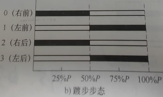
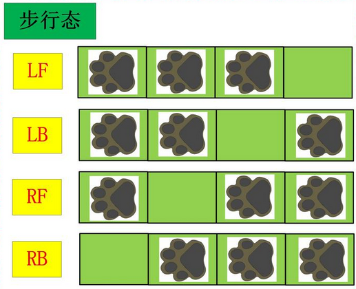
步态就是描述动物走路特点的一种周期性现象。
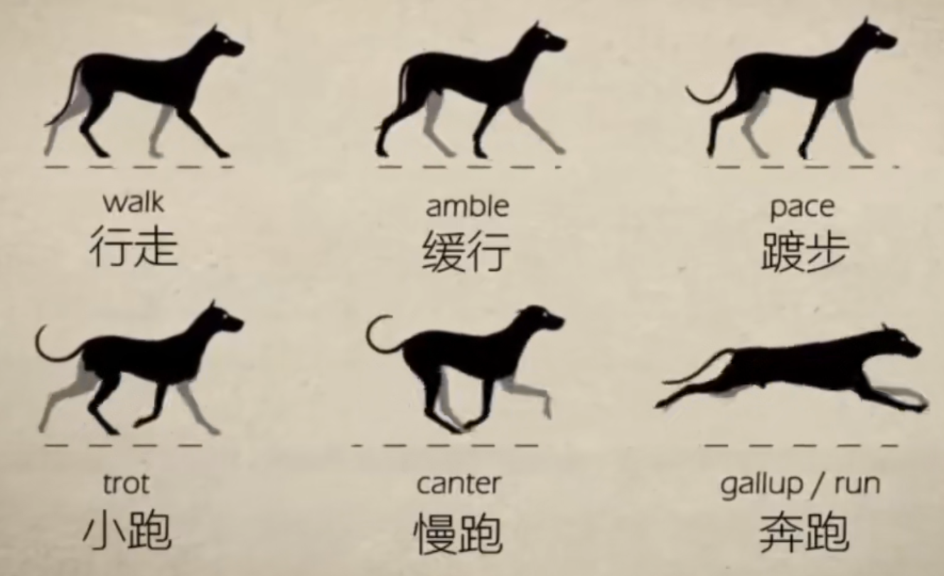
占空比和相位
占空比即每条腿在一个周期内支撑相和摆动相所占的比例,进而用来确定每个时刻,应该有几条腿着地,几条腿悬空;相位用来确定这四条腿运动的先后顺序,也就是时序,只有按照这个先后顺序,机械狗才能做出正确的步态,不然就会非常的混乱。
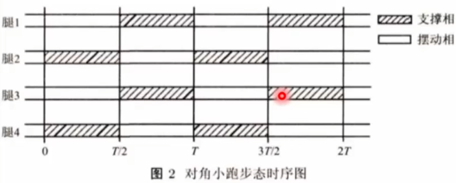
trot步态
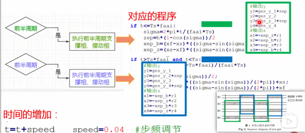
摆动相和支撑相各占一半时间,任意时刻下都有两条腿触地,并且这两条腿分布在机身的对角线方向。
第一步 方程转化为代码
第二步 做出状态切换
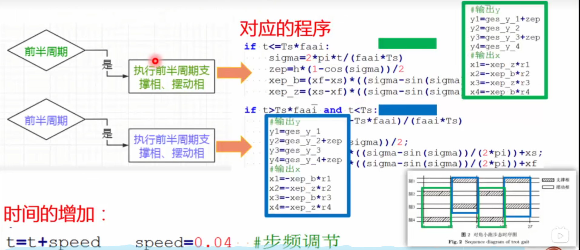
第三步 向电机输出对应的两种步态状态
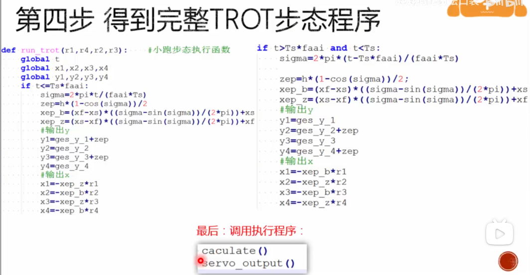
第四步 得到完整的TROT步态程序
webots仿真:
1
2
3
4
5
6
7
8
9
10
11
12
13
14
15
16
17
18
19
20
21
22
23
24
25
26
27
28
29
30
31
32
33
34
35
36
37
38
39
40
41
42
43
44
| #include <webots/robot.h>
#include <webots/motor.h>
#include <webots/keyboard.h>
#include <webots/inertial_unit.h>
#include <math.h>
#include <gaitz.h>
#include <stdio.h>
#include <pid.h>
#include <hardware.h>
#define TIME_STEP 32
#define pi 3.14
int main(int argc, char **argv)
{
printf("START");
wb_robot_init();
hardwareInit();
pid_Init();
posInit();
while (wb_robot_step(16) != -1)
{
t = 0;
while (t <= 1)
{
values=wb_inertial_unit_get_roll_pitch_yaw(imu);
trot();
nijie();
execute();
wb_robot_step(20);
printf("angle:%f Yaw:%f\r\n",angle,values[2]);
t += 0.01;
}
}
wb_robot_cleanup();
return 0;
}
|
1
2
3
4
5
6
7
8
9
10
11
12
13
14
15
16
17
18
19
20
21
22
23
24
25
26
27
28
29
30
31
32
33
34
35
36
37
38
39
40
41
42
43
44
45
46
47
48
49
50
51
52
53
54
55
56
57
58
59
60
61
62
63
64
65
66
67
68
69
70
71
72
73
74
75
76
77
78
79
80
81
82
83
84
85
86
87
88
89
90
91
92
93
94
95
96
97
98
99
100
101
102
103
104
105
106
107
| #ifndef GAITZ_H_
#define GAITZ_H_
#include <webots/robot.h>
#include <hardware.h>
#define pi 3.14
#define TIME_STEP 32
int flag1=0;
int T_s = 1;
float fai = 0.5;
int timestep;
float t = 0.0;
float sigma = 0.0;
float psi_rf = 0.0;
float phi_rf = 0.0;
float psi_lf = 0.0;
float phi_lf = 0.0;
float psi_rb = 0.0;
float phi_rb = 0.0;
float psi_lb = 0.0;
float phi_lb = 0.0;
float thet_rad1_rf = 0.0;
float thet_rad2_rf = 0.0;
float thet_rad1_rb = 0.0;
float thet_rad2_rb = 0.0;
float thet_rad1_lf = 0.0;
float thet_rad2_lf = 0.0;
float thet_rad1_lb = 0.0;
float thet_rad2_lb = 0.0;
float x_rf, x_lf, x_rb, x_lb;
float y_rf, y_lf, y_rb, y_lb;
float height = -19;
float h =9;
float zep = 0.0;
float xep_b = 0.0;
float xep_z = 0.0;
float l_rf = 0.0;
float l_lf = 0.0;
float l_rb = 0.0;
float l_lb = 0.0;
float l_1 = 10.0;
float l_2 = 20.0;
float xs = -10;
float xf = 10;
int r1=-1;
int r2=1;
int r3=1;
int r4=-1;
void trot()
{
if (t < T_s * fai)
{
sigma = 2 * pi * t / (fai * T_s);
zep = h * (1 - cos(sigma)) / 2;
xep_b = (xf - xs) * ((sigma - sin(sigma)) / (2 * pi)) + xs;
xep_z = (xs - xf) * ((sigma - sin(sigma)) / (2 * pi)) + xf;
x_rf = xep_z*r1;
x_lf = xep_b*r2;
x_lb = xep_z*r3;
x_rb = xep_b*r4;
y_rf = 0 + height;
y_lf = zep + height;
y_lb = 0 + height;
y_rb = zep + height;
}
else if ((t > T_s * fai) && (t <= T_s))
{
sigma = 2 * pi * (t - fai * T_s) / (fai * T_s);
zep = h * (1 - cos(sigma)) / 2;
xep_b = (xf - xs) * ((sigma - sin(sigma)) / (2 * pi)) + xs;
xep_z = (xs - xf) * ((sigma - sin(sigma)) / (2 * pi)) + xf;
x_rf = xep_z*r1;
x_lf = xep_b*r2;
x_lb = xep_z*r3;
x_rb = xep_b*r4;
y_rf = zep + height;
y_lf = 0 + height;
y_lb = zep + height;
y_rb = 0 + height;
}
}
|
pace步态
1
2
3
4
5
6
7
8
9
10
11
12
13
14
15
16
17
18
19
20
21
22
23
24
25
26
27
28
29
30
31
32
33
34
35
36
37
38
39
40
41
| void pace()
{
if (t < T_s * fai)
{
sigma = 2 * pi * t / (fai * T_s);
zep = h * (1 - cos(sigma)) / 2;
xep_b = (xf - xs) * ((sigma - sin(sigma)) / (2 * pi)) + xs;
xep_z = (xs - xf) * ((sigma - sin(sigma)) / (2 * pi)) + xf;
x_rf = xep_z;
x_lf = xep_b;
x_lb = xep_b;
x_rb = xep_z;
y_rf = 0 + height;
y_lf = zep + height;
y_lb = zep + height;
y_rb = 0 + height;
}
else if ((t > T_s * fai) && (t <= T_s))
{
sigma = 2 * pi * (t - fai * T_s) / (fai * T_s);
zep = h * (1 - cos(sigma)) / 2;
xep_b = (xf - xs) * ((sigma - sin(sigma)) / (2 * pi)) + xs;
xep_z = (xs - xf) * ((sigma - sin(sigma)) / (2 * pi)) + xf;
x_rf = xep_b;
x_lf = xep_z;
x_lb = xep_z;
x_rb = xep_b;
y_rf = zep + height;
y_lf = 0 + height;
y_lb = 0 + height;
y_rb = zep + height;
}
}
|
walk步态
Walk步态是一种静态步态,即在运动过程中始终有三条腿处于支撑相,至多只有一条腿处于摆动相
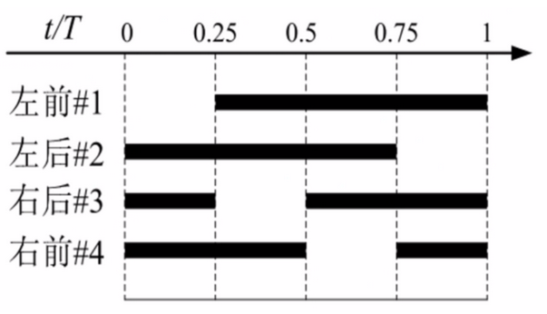
待开发,涉及到相位偏差,后面等把webots程序改成FSM模式后再补……可以先看程序框架里的部分内容有举例。
转向步态
利用差速原理,本质还是trot步态,即一对对角腿在支撑相时另一对对角腿在摆动相,只不过腿运动方向相反。
1
2
3
4
5
6
7
8
9
10
|
x_rf = xep_z*r1;
x_lf = xep_b*r2;
x_lb = xep_z*r3;
x_rb = xep_b*r4;
|
程序框架
参考MIT_CHEETAH开源框架,使用FSM状态机。
首先是main.c文件,while循环只在干一件事情,就是循环执行Dog_Run函数
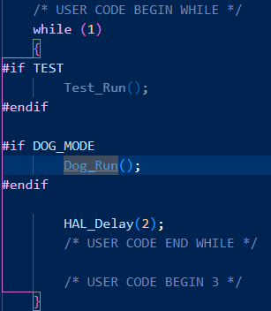
Dog_Run函数如下所示
以下所有程序在Dog_Run函数中循环运行
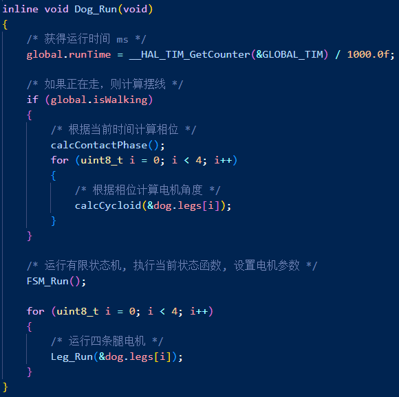
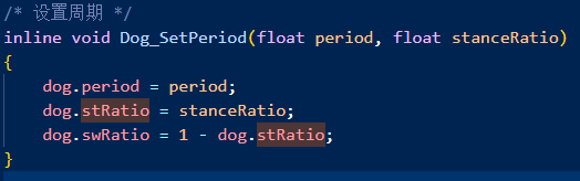
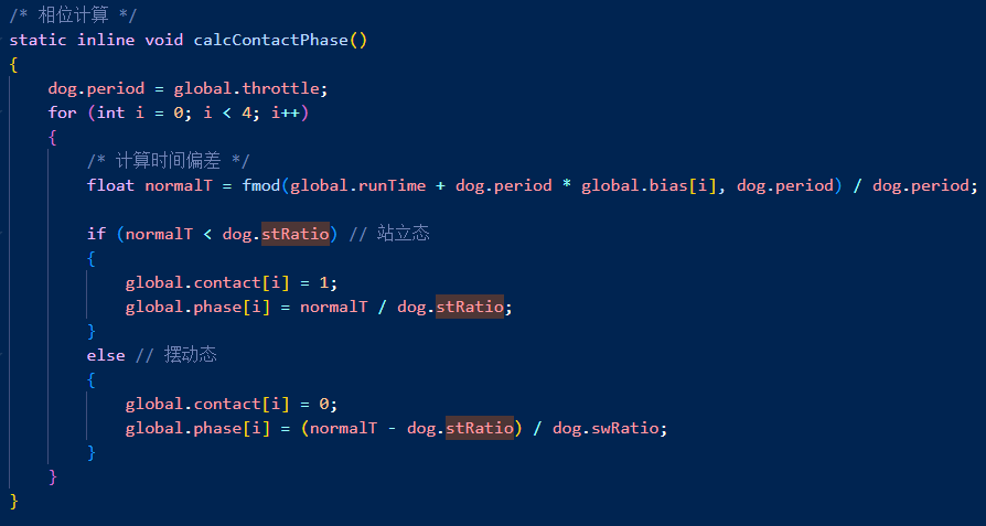
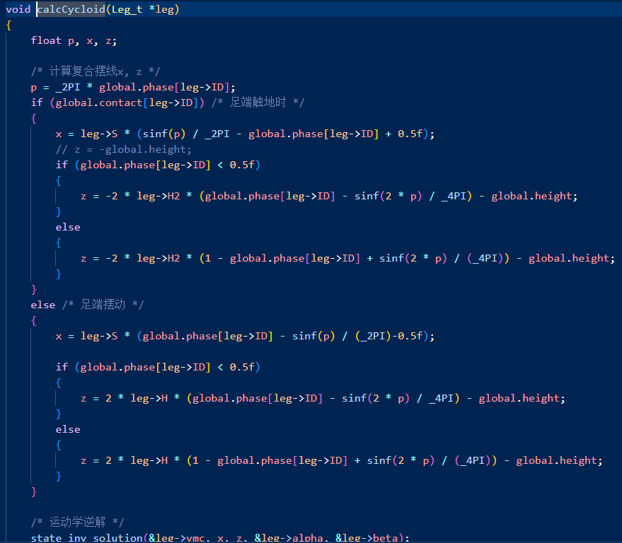
进入FSM_Run后,切换步态,以trot步态为例,首先进入enter函数,通过Dog_SetPeriod函数设置周期(dog.period)和支撑相摆动相在周期所占的比例(dog.stRatio,dog.swRatio),设置global.isWalking为1表示机器人正在行走,开始进行步态规划,计算摆线足端轨迹。
global.bias代表各个腿运动的时序关系
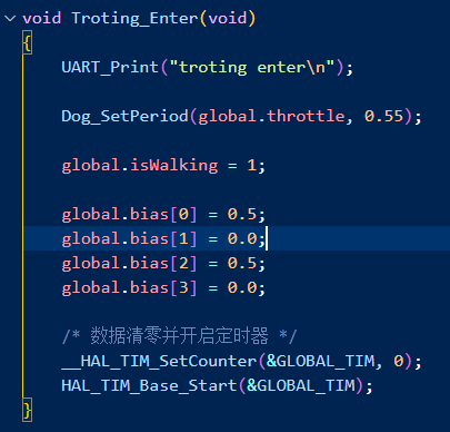
首先进行相位计算,用for循环依次计算每条腿的相位,如果normalT<dog.stRatio,说明在支撑相,global.contact[i]=1,反之在摆动相
1
2
3
4
5
6
7
8
9
10
11
12
|
float normalT = fmod(global.runTime + dog.period * global.bias[i], dog.period) / dog.period;
以walk步态为例:
global.runtime=0
第一条腿:normalT=(0+0.0)%1/1=0 下一时刻0.01<dog.stRatio 支撑相 相位 0.01/dog.stRatio
第二条腿:normalT=(0+0.25)%1/1=0.25 下一时刻0.26<dog.stRatio 支撑相 相位 0.26/dog.stRatio
第三条腿:normalT=(0+0.50)%1/1=0.5 下一时刻0.51<dog.stRatio 支撑相 相位 0.51/dog.stRatio
第四条腿:normalT=(0+0.75)%1/1=0.75 下一时刻0.76>dog.stRatio 摆动相 相位 (0.76-dog.stRatio)/dog.swRatio
double fmod(double x, double y);
|
根据当前相位计算摆线轨迹,p即前面我们方程里的sigma
sigma = 2 * pi * t / (fai * T_s);
sigma = 2 * pi * (t - fai * T_s) / (fai * T_s);

 wechat
 alipay